
 View larger

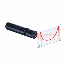
Cosine Correction for Laser
Reference: L2S-COS-Correction
Cosine Correction: To put more power in the extremes of the line than in the center
- Send to a friend
- Remove this product from my favorite's list.
- Add this product to my list of favorites.
 Cosine Correction for Laser
Product description
Cosine Correction for structured light laser line generator
Features of the Cosine Correction
- Large field of view compensation
- Uniform profile captured by sensor
- Excellent for high reflective surfaces
The need of cosine correction
What happens when illuminating with a laser line curved surface?
Imagine for instance that you have to measure or inspect a railroad wheel. The part of the wheel closer to the laser receives much more light than the parts further away.
Or if you have to illuminate the object with a line under a large fan angle?
The extremes of the line shine with much less power than the center. In both cases the result is that the camera can become blinded by the light reflected from the center, or maybe not detect what happens in the extremes. The profile captured by the sensor will have very little uniformity. And if the surface to measure is metallic or very reflective the result is even worse. Under these circumstances it is often used lasers with more power than needed (thus more expensive) or it is required to take very long measurement times, expanding this way unnecessarily the production or inspection times.
We offer the solution
To put more power in the extremes of the line than in the center. This is known as cosince correction or fall-off compensation. Osela is able to provide the desired proportion of power between center and extremes.
In this chart you can see a generic recommendation of the compensation as fucntion of the fan angle of the laser. Of course if the object to be measured is curved the compensation has to be larger.
Angle (º) | Compensation (%) |
10 | 0.98 |
20 | 0.94 |
30 | 0.87 |
45 | 0.73 |
60 | 0.56 |
75 | 0.40 |
90 | 0.25 |
For instance, for a fan angle of 60 degrees it is recomended that the power in the center of the line is 56 % of the power in the extremes.
With the fall-off compensation you can:
- reduce measurement times
- improve the accuracy
- reduce costs (using less power diodes)
- reduce space with the use of larger fan angles keeping the accuracy
Remember that Osela is the only manufacturer of line lasers that polishes in its own factory after coupling them to the laser modules, instead of buy them and match to the modules.
This option is available in all laser modules of the Osela family.
19 other products in category Machine Vision
-
 Optics for Line Laser Systems
 -
 Camera Link Fiber Adapter
 -
 Power Supply
 -
 Switch Splitter Repeater...
 -
 3D Stinger Camera
 -
 Camera Link Fiber Adapter
 -
 Repeater for all Camera...
 -
 Telecentric Laser Projector
 -
 Camera Link Optical Extender
 -
 Mirror 90°
 -
 Camera Link Fiber Adapter
 -
 Bandpass Filter against...
 -
 CL Full Splitter 1 to 4
 -
 Mounting Brackets
 -
 Instrumentation Laser
 -
 3D Stinger Camera
 -
 CompactLine Laser
 -
 StreamLine Laser - SL
 -
 Power adjustment and...